
Program Manager
To create a Control It program that will control a rectifier’s output, select the Programs icon under the Rectifiers tab.
After the Program Manager opens, you will see the programs that Control It already has. If there are no programs, Control It will ask if you would like to create the standard programs. Clicking the Folder Icon ![]() at the top right of the window will create a folder inside of the currently selected folder.
at the top right of the window will create a folder inside of the currently selected folder.
If you click the Add Icon ![]() you will get to choose to make a new program, or a new wizard program. Every program, no matter what type it is, can be customized with preset process details. When you create a process from program, the work order screen will be pre-populated with the default process details already defined for your program.
you will get to choose to make a new program, or a new wizard program. Every program, no matter what type it is, can be customized with preset process details. When you create a process from program, the work order screen will be pre-populated with the default process details already defined for your program.
New Wizard Program
Wizard programs are simple ramp and hold programs that are very easy to make. To make a new wizard program, click the ![]() icon.
icon.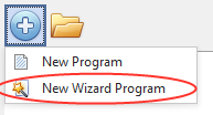

After that, click “New Wizard Program”. You will then be shown a popup that allows you to enter the current density, initial ramp time and the target thickness. The instructions for the program will be displayed as soon as all the necessary information is gathered. Click OK to save the wizard program.
New Simple Program
To create a specific type of control program, click the ![]() icon.
icon.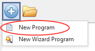 Then click “New Program,” and you will see a new popup asking for the program’s control mode.
- For a voltage control program, the secondary output will be fixed at the rectifier’s maximum output current.
- For current and current-density programs, the secondary output is fixed at the rectifier’s maximum voltage.
Once selected, the program will be added to the selected folder, and you can begin to customize the program in the editor section of the window.
Customizing Simple Programs
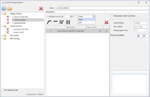 At the top of the editor section, you can enter a name for the program. You can enter a description for the program as well. Below that, there is a checkbox and input for the “maximum floating output.” This setting will control the secondary power of the rectifier. If the program is running on the current or current density control types, the floating output is the voltage. If the program is a voltage control type, you will be able to set the floating output to current or current density by choosing your desired units.
The instructions for the selected program is shown in the grid in the center of the window. Just above this grid, you will find buttons to add an instructions ![]()
![]()
![]() and remove an instruction.
and remove an instruction. ![]()
 Clicking the respective add instruction button will add that type of instruction to the program.
Simple Ramp/Hold Instructions
Clicking the Ramp or Hold buttons 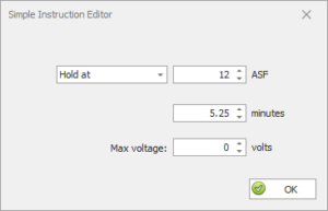 will prompt you to define that instruction. Choosing the Ramp option will add a Ramp instruction to the program that will ramp to the entered target in the entered time. Regardless of the control mode, each instruction set should begin with a Ramp instruction to avoid suddenly jumping the output.
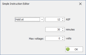 To maintain the output at a specific value, add a Hold instruction. Adding a Hold instruction will pre-populate the target box with the target of the last instruction. The target output will be held for the specified duration. It is not recommended to add a Hold instruction with a target greater than the target of the last instruction, as this will surge the output to the target immediately when the instruction takes place, and again, this could potentially burn your parts.
Pulse Instruction
 Choosing to add a Pulse instruction will bring up another window. In this form, you can fully customize the pulsing profile of the instruction. You can enter the high and low outputs that the instruction will alternate between, then you can also decide how long it stays at each state, and how many cycles will be performed by the instruction. Lastly, you can add a ramp time to allow your rectifier to slowly ramp from the low point to the high point to avoid sudden output jumps.
To edit any program, simply select it in the Program Editor, then click the gear icon ![]() on the instruction you wish to change. Editing a Ramp instruction will allow you to change the desired output for that instruction and/or the time required to reach the output. Editing a hold instruction allows you to change the time of the instruction, as well as the target output.
on the instruction you wish to change. Editing a Ramp instruction will allow you to change the desired output for that instruction and/or the time required to reach the output. Editing a hold instruction allows you to change the time of the instruction, as well as the target output.
To remove the any instruction, click the Delete icon ![]() next to the instruction.
next to the instruction.
Instructions can only be added to the end of the instruction list. You may not add an instruction to the beginning or middle of the list.

To create a program that will control a rectifier’s output, select the Programs > Manage Programs menu item.
After the Program Manager opens, right click the folder to create a program and select New Program. If you need create a folder, select New Folder and a new folder will be created inside the selected folder.
Selecting New Program will open the Program Editor allowing you to build your program .
 After the Program Editor opens, enter a name for the program. You can enter a description for the program as well. Next, select either Voltage, Current or Current Density as the control mode from the drop-down menu. Control-It is capable of controlling the rectifier’s voltage and current during a process. This allows you to ramp a program to a particular current and at the same time not allow the voltage to exceed a specific set value.
If you choose a voltage control mode, you will be entering the voltage instructions in the pane on the left. These instruction are referred to as the program’s primary instructions. Current control instructions are referred to as secondary instructions and are entered in the right pane. If the control mode is current or current-density, the current control instruction are primary, voltage instruction are secondary and the sides they are enter inn are reveresed.
A note regarding secondary instructions:
You do not have to include secondary instructions. If no secondary instruction are entered, the secondary output is assumed to be the rectifier maximum output. For voltage control, the secondary output will be fixed at the rectifier’s maximum output current. For current and current-density programs, the priamry output is fixed at the rectifier maximum voltage.
Regardless of the control mode, each instruction set (both primary and secondary) must begin with a Ramp instruction. Clicking the Ramp Button  will add a ramp instruction to the program. You will then be asked to enter output you would like to change to followed by the amount of time it will take to reach the desired output.
To maintain the output at a specific value, click the Hold Button  . You will then be asked to enter the amount of time to maintain the output. You can also add a Pause instruction to the program. When a pause instruction is encountered while a program is running, the rectifier outputs will be set to zero volts and zero amps and the general alarm will be activated to alert your operators. To add a Pause instruction, click the Pause Button
  While a program is paused, the operator can pull the load out of the tank and check the coating thickness. If the parts need more processing time, the operator can resume the program.
You can add multiple instructions very quickly by defining a pulse profile and adding it to the program. A pulse profile is like a small sub-program that can added to a program and allows you to quickly build slow pulse anodizing programs. Please see Managing Pulse Profiles for details.
To edit any, simple double clicking the instruction. Double-clicking a ramp instruction will allow you to change the desired output for that instruction and/or the time required to reach the output. Double-clicking a hold instruction allow you to change the time of the instruction. Note that if you change the output of a ramp instruction, all of the following instructions will be changed by the same amount. So if a ramp instruction was change from 14 volts to 15 volts, the output of every following instruction will be increased by one volt. To remove the last instruction, click the Delete Button  .
.
You cannot insert instructions in the list. Instructions can only be added to the end of the instruction list. Likewise, only the last instruction can be removed.
If secondary instructions are used, the primary and secondary instruction sets must be reconciled. Reconciling the instructions ensures that both instructions set have the same total processing time. After entering all of the instructions, click the Reconcile button over the seconardy instruction set to reconile the program. If the instruction set are not of equal length, the program will attempt to reconcile itself if the last secondary instruction is a Hold instruction. In these cases, reconciliation occurs by adjusting the time of the last secondary instruction. If the last secondary instruction is not a hold, the program will not reconcile itself. For this reason it is good practice to end the secondary instruction set with a hold instruction.
A program must be reconciled before it is saved.
You can also include information with your programs. If you have a program that is for a particular part, you can include the part number and customer name with the program so your operators will not have to enter the information every time they run the program. To add information to a program click the Data Fields button from the program editor. Before adding data to a program, you must configure the data field first. Please see Managing Data Fields for details.
After click the Data Fields you can add data to the program button in the window that appears. Available data fields are shown in the list on the left side. Double-clicking a field in list will add it to the program. After adding a field, enter the value it should be when the program is run. If the value will always be what you enter, then by selecting the Fixed option, the operator will not be allowed to change the data. If most of the time the value is what you entered, but sometimes it changes, leave the fixed option unselected and the operator will have the opportunity to change it.

