
 Control It supports most rectifier manufactures and their configurations. Some rectifiers require a PLC, while other rectifiers can be controlled directly using an Ethernet connection. To set up the hardware for a PLC or rectifier, the computer running Control It and the rectifier or PLC need to be connected. Once the connection is established, the rectifier’s settings can be configured.
Whether you are connecting to a PLC or to a rectifier directly, you will need the IP address to configure it. For PLCs, the IP address can be found on the inside of the PLC enclosure. For direct connection to a rectifier, please see to rectifier documentation to obtain the IP address.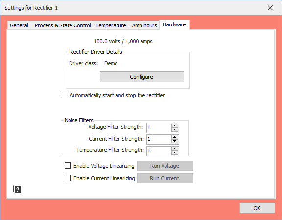
Start by clicking on the Settings button for the rectifier you wish to configure. Once the rectifier settings window appears, navigate to the rightmost tab labeled “Hardware.” From there, click Configure, and you will see a window appear with a drop down list with several hardware options that are built into Control It. Each selection of this list will be configured in a different way, so here are some quick links to the section for each hardware type:
NOTE: Connecting to a rectifier or PLC will require that rectifier to be on the same network as the Control It computer. While it’s possible to configure the computer Ethernet to use multiple IP addresses, Mickabooh recommend that all rectifier and PLC connections be made using a dedicated connection. More info about changing network settings for Windows.
For ACRS hardware, the IP address of the rectifier must be provided. After entering the correct IP address for the rectifier, click the Initialize button. If the configuration is incorrect, there will be a message indicating as such. If the configuration is good, there will be a dialog window that shows up asking if you would like to keep this configuration. Selecting yes will finish the driver configuration. The maximum current and voltage will then be read from the rectifier and displayed on the configuration window. You may now close the window.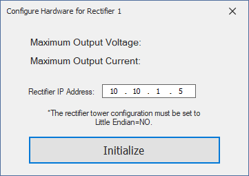
For Opto22MMP hardware, the IP address of the PLC must be provided. After entering the correct IP address, the rectifier will also need to be configured with a controller number. The controller numbers are labeled and can be found by opening the PLC box and looking inside. Once the IP address and controller number are both set for the rectifier, click the Initialize button If the configuration is incorrect, there will be a message indicating as such. If the configuration is good, there will be a dialog window that shows up asking if you would like to keep this configuration. Selecting yes will finish the network configuration, however you must set the maximum current and voltage of this rectifier. You may now close the window.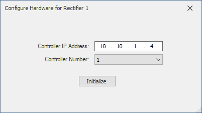
Older rectifiers may also need an additional step to ensure their outputs are accurate. This step is called linearization, and it is recommended if your rectifier’s output is noticeably off from the program’s set point. You can read more about this configuration step on the Linearizing Rectifiers page.